Enabling superior storage efficiency for Type 4 tanks with FPP dome reinforcements
Composite pressure vessels (PVs) are the key storage system for hydrogen-powered mobility. Automation specialist Cevotec has developed an industrial solution that, in combination with the established filament winding (FW) process, improves the material efficiency significantly by reducing the composite fibre material consumption of a tank approx. 15% or more while simultaneously increasing the available storage capacity. This article has been published in the JEC Composites Magazine N°147.

The number of countries committing to emission neutrality by 2050 is growing. Deploying hydrogen (H2) as an energy carrier is a promising approach to achieve this goal, especially for the transportation sector. Fuel cell electric vehicles (FCEV), in particular for long-haul transport systems such as trucks, buses and trains, as well as hydrogen-related aircraft programmes, are on the rise. One of the challenges is to efficiently and safely store hydrogen for mobility applications. H2 is typically stored in Type 4 pressure vessels, which have a very high consumption of carbon fibre material due to their working pressure of up to 700 bar. This negatively influences the production costs of hydrogen pressure vessels, with carbon fibres representing over 50% of the total tank costs. To decrease the material consumption, Cevotec developed an industrial automation solution to reinforce the domes of pressure vessels, using Fibre Patch Placement (FPP) technology.
Tank reinforcement with FPP technology
PVs are typically manufactured by winding filaments of impregnated fibres around a polymer liner with different principal fibre orientations, as shown in Figure 2. The primary stresses in the tank laminate are in the circumferential and longitudinal directions, which are covered by the hoop and low-angle helical layers (LAHL). The high-angle helical layers (HAHL) significantly absorb the stresses that occur in the boundary area. In the cylindrical region, however, the fibre orientation of the HAHLs deviates from the main stress direction, so only a small fraction of their load-bearing capacity is used.

©Cevotec
Due to the continuous winding process, however, they cover the whole tank and not just the dome area, which leads to a considerable amount of inefficiently used fibre material. As a solution, the HAHLs can be replaced by local dome reinforcements. The reinforcements only contribute to the dome area, as shown in Figure 3, while the cylindrical part is then covered only by the hoop windings and LAHLs. This approach was originally suggested by the US Department of Energy in 2013. But at that time, there was no industrial process available that was able to produce those reinforcements efficiently. Cevotec’s Fibre Patch Placement is the first technology to lay up dome reinforcements directly onto the liner using a fully-automated, industrial process.

©Cevotec
This can be combined with established wet or tow winding equipment. The magnitude of the potential benefits of dome reinforcements depends on the principal geometry of the vessel. Since FPP dome reinforcements replace HAHL orientations from the cylindrical portion of the PV, the benefits of this solution increase as the length/diameter aspect ratio increases, since inefficiently used material is removed from a larger cylindrical area.
Development process overview
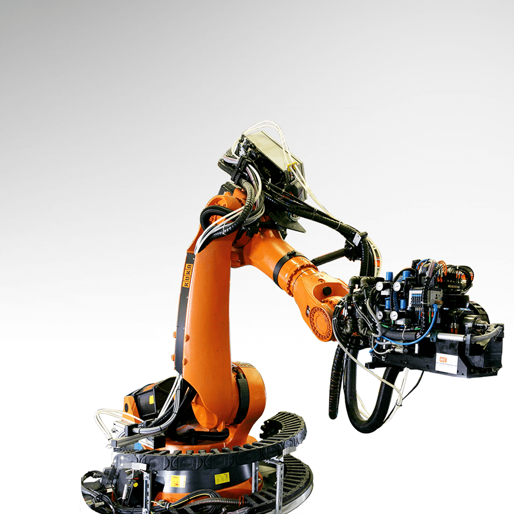
After designing the PV in a standard CAD software, the geometry is imported into Cevotec’s Artist Studio software, where the entire virtual design and production planning process takes place. The first step is the creation of the virtual laminate. Each of the HAHLs to be replaced is defined using the Patch Artist CAD module. The laminate is designed using the built-in curve creation algorithms. This results in a system of guide curves being virtually placed on the PV CAD model. Patches are created on every curve with a defined length and width. Transverse and longitudinal overlaps for the patches between layers are optimized to ensure structural strength. During the virtual laminate creation step, the thickness distribution can be monitored and calculated in real time, facilitating efficiency in laminate design iterations. The next step in the virtual process development is to generate the offline robot program and perform a process simulation. The created FPP laminate is transferred from the Patch Artist module to the Motion Artist CAM module, which features the digital twin of the production system. The programming of the production system robot is fully automated and efficiently generated. The complete manufacturing process can then be simulated, including an automated collision check, with the goal to ensure safe operation of the FPP production system. The final step is the actual manufacturing of the dome reinforcement using Cevotec’s SAMBA Pro PV FPP system (Figures 5 & 6).

©Cevotec
This newly-developed automation system is optimized for the manufacturing of PV reinforcements. After the machine program is loaded into the SAMBA system, material in tape form is fed and used by the system to cut patches of the chos en geometry. Each patch is first checked by a vision system for geometrical accuracy and defects. The patches are then pickedup by Cevotec’s form-adaptive gripper mounted at the placement robot. Each picked-up patch is inspected again to ensure…
Want to read the end of the article?
Register now and access to the entire article published in the JEC Composites Magazine N°147 !


