[BEST OF 2023] Composite manufacturing like Lego® blockswith precision preforming
Wind turbines are getting bigger and bigger, and the industry is challenged for more cost reductions and higher production efficiency. At the same time manufacturers are facing high quality criteria that come at cost. Rotor blades are typically almost a third of the cost of a turbine, and currently have a high labour content in the manufacturing process. The obvious question which come to mind is: “Can the manufacturing process be automated?” This article has been published in the JEC Composites Magazine N°151.
![[BEST OF 2023] Composite manufacturing like Lego® blockswith precision preforming](https://www.jeccomposites.com/wp-content/uploads/2023/07/CCEA-630x500.jpg)
The answer is both commercial and technical. Adopting preform technology could be the answer. To automate the process, the manufacturing process of blade manufacturing should be addressed as an assembly process, where today’s processes are often seen as a moulding one. The manufacturing of a rotor blade can be changed by assembling precision preforms at the right place with the right quality. In this article RewAir shares the work done so far, knowing the study has not been finalised yet.
Automation and tolerances
In past decades there have been various initiatives to automate rotor blade manufacturing. Typically, the approach was taken to automate the full ply layup in the mould. Large, automated gantry systems were the preferred method chosen, but when looking at the Return on Investment (ROI) the number of parts produced, during the blade lifetime, made it difficult to justify commercially. The wind industry is increasingly known for short product cycles and small volumes. This makes full scale automation from a ROI and output point of view almost impossible.
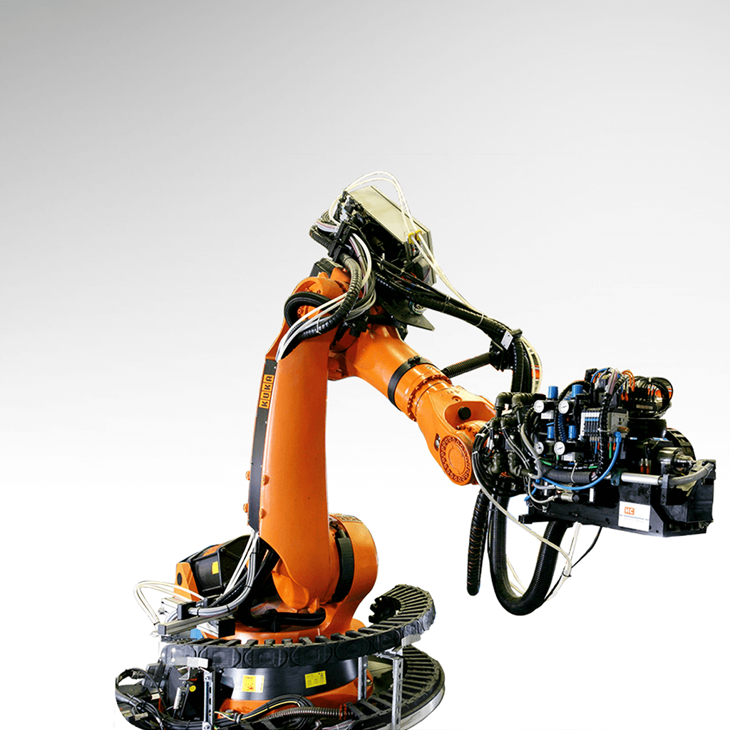
The preforming concept -building small units that can be placed in predetermined sequence into the mould- requires a simple “pick and place” unit, with the flexibility for a variety of blade and nacelle designs and shapes. To obtain economies of scale, all small preforms can be built by a single central location, thus creating a higher utilisation of investments. With the fact that the supply chain for building preforms can be increased as needed, the positive effects for the industry are evident.
Preforms have been supplied to the industry for rotor blade manufacturing by RewAir for many decades. The majority of the preforms produced are stitched. However, to meet the increasing automation demands of the industry, the company now aims at enabling that with precision preforming. To enable the proper placement of the preforms it is essential that the accuracy and tolerancing of the preforms is high. Special focus is required on the overlap between the preforms as well as on positioning in the mould. For precision preforming RewAir is currently investigating the application of automated ply layup to ensure the accuracy and tolerancing needed (Figure 1).

Precision preforming study
In the precision preforming study carried out, a method to break down large composite structures into smaller units has been investigating. This approach views the manufacturing process as a series of assembly processes, not just a moulding process. For this we have taken the most critical part of a rotor blade, the sparcap.
This structure sees the highest mechanical loading in both tensile as well as compression loads and is typically made of long unidirectional fibres. We are aware that a sparcap is probably not the first part to be replaced by preforms. However, to understand the constraints best, the most demanding component (worst-case scenario) was deliberately chosen.
Making a sparcap in two halves has two main challenges, firstly, the strength of the joint in comparison with a non-split part, and secondly, the accuracy, or tolerances, of the fibres to be placed. The tolerance of the joint is expected to have a direct impact on its strength.
Proper design and engineering are fundamental and opens up opportunities to find a solution. Our study showed that more compact joints can be designed and are possible when engineering and simulation is part of the process. The initial joint design length was reduced by >60% while maintaining the required load capacity of the sparcap.
The solution has been achieved by making dry preforms to the required tolerances and dimensional accuracy with a tapered step joint (Figure 2), between the two sparcap halves being assembled. Using numerical calculations, a double slope step joint topology has been selected as the preferred joint.

The numerical analysis has been compared with test samples that were produced using preforms infused with epoxy resin, mimicking the production conditions of real wind blade manufacturing. The preforms were made manually, but with aids to simulate an automated process. Every process step was controlled and checked.
Material choice and application
Any change in a material usually has a high impact on production, as well as the qualification of the material. For that reason, we have looked at known glass fabrics with a proven track record in the wind industry. For making preforms there are various recognised technologies (Table 1).

For precision preforming, based on these five technology options, the choice of using a powdered preform is the most logical for economic reasons, which also has a proven track record in the industry. The powder used as a binder has a glass transition temperature (Tg) within the infusion process curing temperature range, so does not create any processing issues.
The powder has been applied by the fabric manufacturer in an automated way to ensure that the binder is evenly distributed on the fabric and therefore matches the highest quality requirements.
The precision preforming comes with additional material cost, plus the need for tooling and processing. Therefore it is recommended to do a cost-benefit analysis to identify where the application of precision preforms brings most benefits in large composite structures. In other sections, continuing to use stitched preforms (Figure 3) may be more economical. The laminate plan of a blade is driving these choices, and RewAir supports customers in evaluating the best options and ultimate choices.

Testing setup and results
A series of tests including 5 specimen without a joint (“pristine” samples) have been compared to a series of 5 specimen with a double scarf joint. Testing specimen size, material and layup composition were customised. The size was maximised to provide a representative joint that could fit in the available testing equipment. Test samples were loaded with signifi cant test load (>400 kN). All samples were tested under static load conditions to the ultimate tensile strenght (UTS). Different parameters were monitored using strain gauges and load cells. The testing was performed by an independent DNV approved test institute with extensive experience in testing composites.
The results of the testing for the “pristine” samples were used to provide a benchmark of both processing and the engineering assumptions. Testing showed a very good consistency of…
Want to read the end of this article?
Subscribe for free now and access to the entire article published in the JEC Composites Magazine N°151. Available in print, digital and via the mobile application.









![[BEST OF 2023] Composite manufacturing like Lego® blockswith precision preforming](jpg/ccea-630x500.jpg)
