


Composites play starring role in humankind’s largest space telescope
Capturing otherworldly images and heretofore unknown knowledge of the universe, the James Webb space telescope incorporates many composite material innovations. This article has been published in the JEC Composites Magazine N°151.

Time machine to the cosmos. Built by our world to discover new worlds.” These are just two phrases from Northrop Grumman, lead contractor for the James Webb space telescope (Webb), to describe humankind’s largest space telescope ever made. Webb is discovering new star systems and gathering scientific evidence about cosmic history from its observatory position 1.6 million km away from Earth (Figure 1). Webb is a great engineering feat of this era, and composite materials literally play a major supporting role.

Webb must meet unprecedented thermal stability requirements to minimize changes in its shape while one side is hot from facing the sun, and one side must perform at ultra-low cryogenic temperatures.
“It’s just amazing to see the images coming back from Webb, and to know that they are made possible, in part, by using innovative graphite composite technology that our team developed just for this mission, said Bob Hellekson, program manager, Northrop Grumman. That technology has enabled a world-class, nanometre-stable, foldable, deployable and mass-efficient telescope that is ushering in a new era of astronomy.
Webb composites innovation
Northrop Grumman’s composites group provided the following Webb hardware:
- Primary Mirror Backplane Support Structure (PMBSS), or Backplane, and Wing Structures;
- Secondary Mirror Support Struts (SMSS);
- Secondary Mirror Mount Assembly (SMA);
- Star Tracker Support Assembly (STSA);
- Deployable Tower Assembly (DTA);
- Sunshield Side Booms;
- Sunshield Spreader Bars;
- Spacecraft Bus System Propulsion Tanks;
- Integrated Science Instrument Module (ISIM) Structure.
Webb has two primary sections, the ISIM/Optical Telescope Element (OTE), or OTIS, and the Spacecraft Bus (Figure 2). OTIS This Webb section contains the telescope’s 6.5-metre (m) diameter primary mirror,
secondary mirror and the missioncritical telescope optical equipment and scientific instruments.

- Backplane (Figure 3). Made primarily of M55J graphite composite material, the Backplane is approximately 7.3-m tall by 6.1-m wide. Also known as Webb’s spine, the PMBSS composite structure supports about 3,311 kgs of mirrors, telescope optical instruments and other OTIS components (Figure 4). The weight supported by the Backplane is more than three times its own weight. A major design challenge was the requirement for OTIS to remain still and stable at ultra-cold temperatures, or else the optical equipment could not function optimally. To accomplish this feat, the Backplane’s materials could not expand or contract more than 38 nanometres (nm) root mean square (RMS), which is about 1/1000 the diameter of a human hair over the range of operational temperatures. A new composite laminate was designed to meet this demanding coefficient of thermal expansion (CTE) specification from room temperature to the 50 Kelvin (K) to 30K operating temperature range, or about -223°C to -243°C. The material must be stable to 38 nm RMS over this operating temperature range within a tolerance of +/-0.15 K. “The Backplane had to be strong enough to survive the vibration and stresses of launch but still be flexible enough to handle the shrinkage and structural loads that can occur at cryogenic temperatures”, said Hellekson (Figure 5).

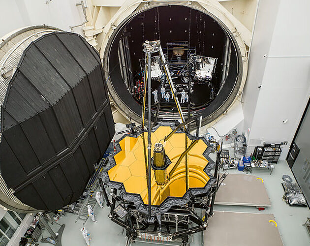
Fig. 4 (lower left): Webb’s Backplane is a large composite structure, which supports 6 tons of instruments, mirrors and telescope components. © NASA
Fig. 5 (lower right): Webb’s composite Backplane is open to its full width as a robotic arm installs the fi rst of 18 primary mirrors. The mirror surface is covered by a black protective layer here. © NASA
- Extensive composite joint development testing was required for most Webb composites. For the Backplane and instrument carrier, a unique requirement was to prove joint integrity and strength at the extreme cryogenic temperatures achieved during Webb’s deployed science mode, said Lee Feinberg, Webb telescope manager, NASA Goddard Space Flight Center (GSFC). “All composites worked extremely well, Feinberg said. The stability of the telescope is exceeding expectations.”
- Northrop Grumman’s composites team found that connecting carbon fibre with titanium and invar fittings and interfaces gave the Backplane stable strength even as the dissimilar materials react differently to temperature changes in Earth’s atmosphere and space. The composite parts were tested before assembly in a cryogenic chamber at 5K —near absolute zero— and the changes in dimension were measured (Figure 6).

- DTA (Figure 7). The DTA helps the telescope and instruments to fit within the rocket fairing with an acceptable centre of gravity for launch. Then after launch, as Webb transitions to its deployed configuration, the DTA lifts the telescope mirrors and instruments away from the spacecraft. It extends from its stowed height of 1.7 m to a fully deployed height of 2.9 m. That consists of two large telescoping tubes, made primarily of a lightweight graphite composite material chosen for its ability to thermally insulate the cold telescope from the hot spacecraft . “The DTA involved some very complex geometries”, Hellekson said.

and later lifted the telescope up and away from the Spacecraft Bus. © Northrop Grumman
Spacecraft Bus Structure
This portion of Webb includes the Sunshield, which is crucial for keeping light and heat from the sun, Earth and moon from the telescope’s science instruments so they can operate in darkness at approximately 50K. It also includes the Spacecraft Bus Structure, which contains guidance, navigation and communications systems. For this Webb section, composite materials were chosen primarily for their light weight rather than for their performance at cryogenic temperatures.
- Sunshield For the five-layer, 21-metre long, 14-metre wide sunshield, component material selections were completed at Webb’s preliminary design review in early 2008. Initially M55J was selected for the 9-metre Sunshield Unitized Pallet Structures (UPS) and other components that support large expanses of Kapton material, which blocks heat, light and infrared radiation from reaching OTIS. However, after critical design reviews, NASA saw it needed to significantly reduce Webb’s mass. This led to changes in materials for several significant subsystems, including the Sunshield UPS, which ultimately were made of M60J high-modulus carbon fibre to reduce mass. The large UPS structures needed to be lightweight, stiff and creep resistant.
- Layers of T300 carbon fibre composite make up the Sunshield’s 5-m Mid-Boom Assemblies (MBA), which were laid up into a series of telescoping tubes with reinforcing rings.
- The UPS and MBA structures had to carry the Sunshield membranes in their stowed condition for launch, then deploy and tension the membranes on-orbit and now maintain that tension throughout Webb’s five-year to 10-year life. They must withstand continuous bending loads at temperatures >100°C while keeping the membrane positions stable. “Extensive creep testing on MBA and UPS composites proved they would remain dimensionally stable during long-term exposure”, said James Cooper, Sunshield manager, NASA GSFC.
- STSA “On the Spacecraft Bus Structure, the STSA was the most challenging composite component”, said Jeff Smallowitz, Webb Spacecraft Structure and Mechanical lead, and president, Matrix Solutions Inc. The STSA supports three star trackers in precise alignment to orient the observatory as it collects scientific data. Though the STSA was designed to operate near room temperature, the tiniest thermal gradients would distort the structure and affect observatory alignment. As a result, the STSA required ultra-low CTE laminates and a thermal enclosure to maintain the hardware at a uniform temperature.
Discover more videos on JEC Composites Web TV.
Over 1.6 million km away from Earth, composite materials are essential to Webb’s search for answers to the beginnings of the universe and the discovery of new worlds. For the international, multidisciplinary team that brought Webb to fruition, in many ways, a major mission has already been accomplished.
Read the latest JEC Composites Magazine:
Subscribe for free now and access the entire JEC Composites Magazine N°151.
Available in print, digital and via the mobile application.


You can create a free technological watch and keep you updated about all these subjects.